HOME MIDI boards Modular synth Polysynth DSP Links history
Pulsoburster

This is little circuit inspired by 5Pulser Waveform Generator of Ian Fritz. Ian uses bargraph controller to achieve his goal. Unfortunately I couldn't find this chip in SMD, and being SMD-freak that was enough encouragement to find another solution. The circuit has to generate pulses of variable length and quantity depending on control voltage. One can do it with several comparators, but to have, say, 5 pulses per cycle, 10 comparators are needed. Using dot-mode bargraph controller like Ian has used, simplifies the core circuit to one IC. But maybe the same thing can be done with one comparator working at jumping levels:
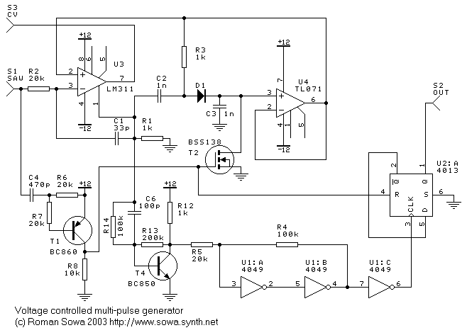

The circuit takes any external signal with not too slow fall time of waveform (ideally a sawtooth), but can be simplified if it's used as part of common type VCO.
HOW IT WORKS:
Let's assume at t=0 no caps are charged and incoming voltage is somewhere below 0V. When input signal crosses 0V, comparator toggles and charges C3 via D1 and C2 "a little bit" (technical term). Follower U4 sets up new, higher voltage to comparator's (U3) other input, so it can go low again. C1 and R2 form short spikes in positive feedback, so it can stay high long enough for C3 step-charging. (When using pin 1 of LM311 as output, its inputs work reversed). Then input has to raise the same "small bit" before comparator reacts again.
The same comparator pulses, that charged C3, are used to form output pulses. They are first formed in amplifier built arount T4, and then transients are formed using NOT gates. Uniform pulses toggle divider by 2 made of D-flop U2:A, so we get nice 50% duty pulses at the output.
Circuit around T1 is used to detect begining of cycle, e.g. falling ramp of sawtooth wave. Pulses from there reset step-charged C3 at the begining of every cycle using T2 MOSFET. The divider by 2 is also reset by those pulses, so output starts always at level high, no matter if there was even or odd number of pulses in previous cycle.
Now, the deal was to have it all under voltage control. If we apply variable voltage to pin 7 of LM311 comparator, its output pulses will have varying amplitude. Higher spike can charge C3 faster, so as a result there are fewer bigger steps at C3 then there would be when small U3 spikes are present.
Example: at cycle frequency 2kHz, there was 1-15 pulses per cycle (ppc?) when control voltage changed from 12 downto 1.2V. At lower frequencies it works somewhat better. Lowering CV to 0.7V resulted in about 80 pulses per cycle.
This was a test circuit, and I'm sure there's lot to improve. In actual circuit, built on solderless breadboard, I used OP249 as opamp, and HC04 instead of 4049, both HC04 and 4013 were supplied from 5.5V, and transistors were their thru-hole counterparts - BC549 anf BC 559. As input I used "almost-saw" uneven-ramps triangle wave from testlab generator. It is recommended to use input signal symetrical around 0V in order to get 50% duty cycle of pulse bursts.

And now, what you've been waiting for - the samples. WAV are 44.1k 8bit, MP3s are 32kbps, just for those with slow connection, wavs are much better.
first one 170KB mp3, or in wav format 1.8MB - sweeping pulses
second one 230KB mp3, or in wav format 2.5MB - second part, base frequency changed
third one 120KB mp3, or in wav format 1.3MB - when D-flop (U2:A) is not reset at begining of each cycle

See also uglyface and 5-pulser.
HOME
MIDI boards Modular synth Polysynth DSP Links history
© 2021 Roman Sowa
last modified January 2004