So this is the core of VCO, and it works only because RRIO opamp is there.
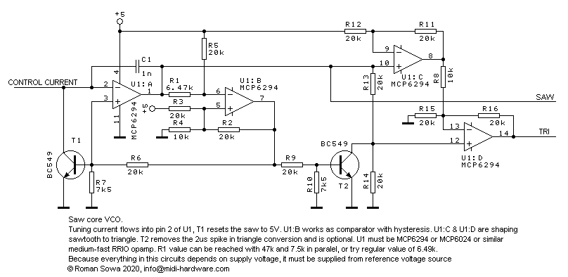
And this is how it works. Lets start from a state when C1 is fully charged and U1:A output is at 5V. Control (tuning) current flows into the node of inverting input, at 0V. It discharges C1 capacitor, so voltage at U1:A falls down. U1:B is used as comparator with relatively big hysteresis, which is the key to frequency and amplitude stability. At this state the threshold of U1:B switching is at 1/4 of supply voltage (voltage divider R2||R4 at bottom and R3 at top). So when U1:A is reaching nearly GND, the other voltage divider (R5 - R1) is also closing to 1/4 of supply voltage. After reaching the threshold U1:B goes up, and turns on T1 transistor. That shunts to GND the current path that we need to quickly charge C1 capacitor, and its base voltage overloads input of U1:A making it go high as quickly as it can, limited by SR parameter (7V/us for this opamp). During that rise the threshold of comparator changes, slowly (in a manner of microseconds speaking) reaching 1/2 of supply voltage. U1:A will finally cross that too and U1:B can go low again. During that process the transistor is open long enough to fully charge the capacitor and U1:A hits 5V supply rail. At this moment U1:B was already going back to GND, which turns off T1 transistor and discharging from control current may start again.
Frequency of this VCO directly depends on supply voltage - the higher the voltage, the more charge is injected into capacitor during reset stage, so it takes longer to approach GND. So obviously it must be powered from stable voltage, like reference source. It does not have to be 5V, although 5 is nice number. With values shown it works down to 3V. By adjusting R7 and R8 properly one could go at lower supply. With TS912 opamp it was working even at 1.25V supply voltage.
And this is how first prototype looked like:
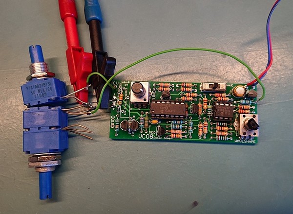
It's easy to notice there are more transistors in there. That's because the board already contains simplified (single supply of course) dual-transistor expo converter, one-transistor VCA, and one more transistor which is not needed in final version. The other dual opamp is used for VCA and ramp waveshaper. None of those additions will be described here, let's focus on VCO core first.
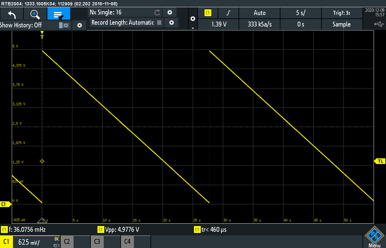
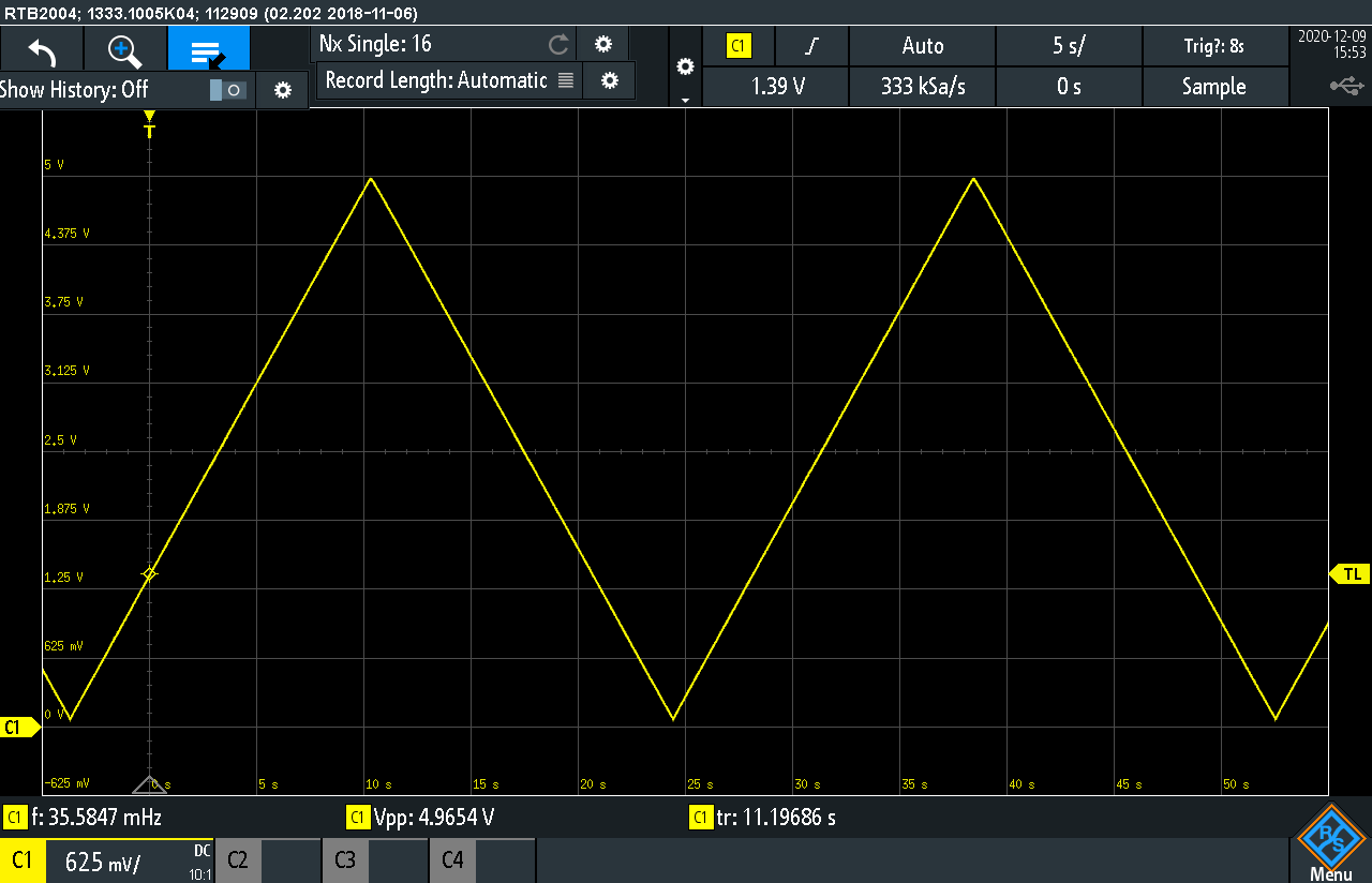
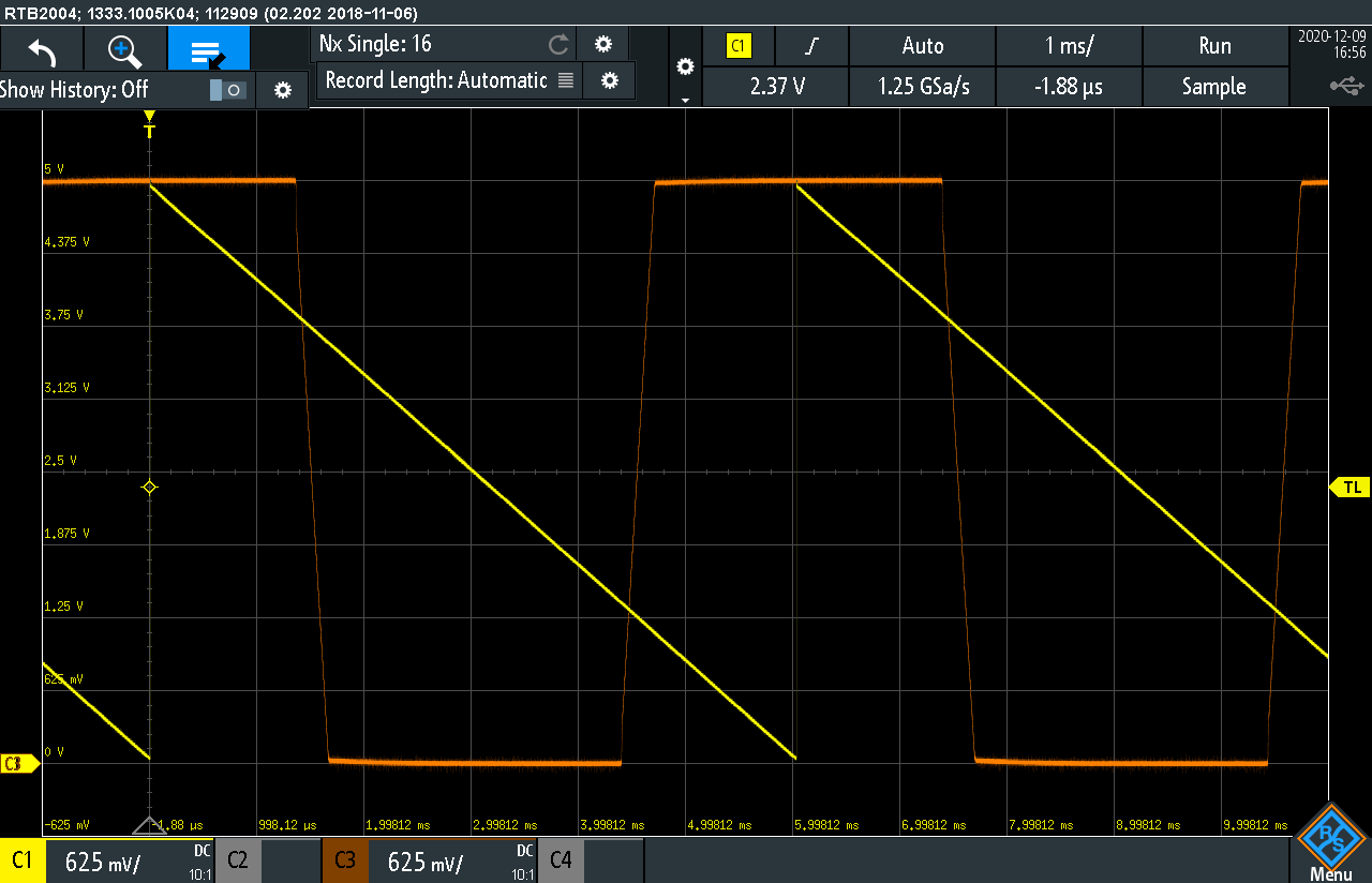
And now it's time for some scopeshots (right-click the image - show picture for full resolution):
| SAWTOOTH | TRIANGLE |
| Lowest frequency. It can go lower, but waiting couple of minutes for single shot is impractical | |
 |  |
| 1Hz | |
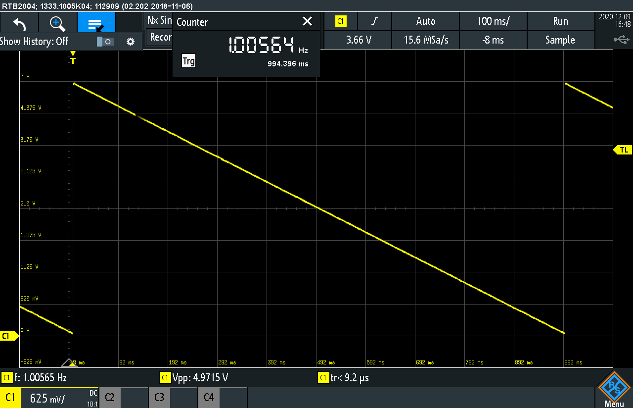 | 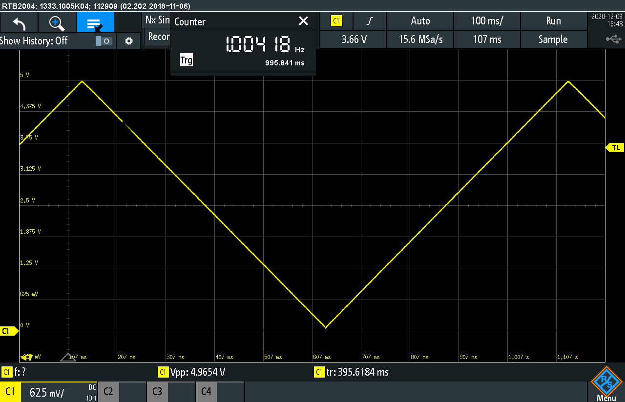 |
| 100Hz | |
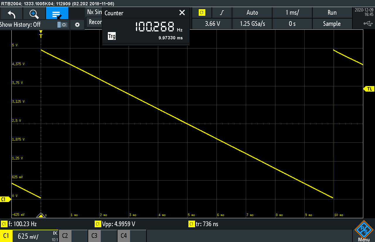 | 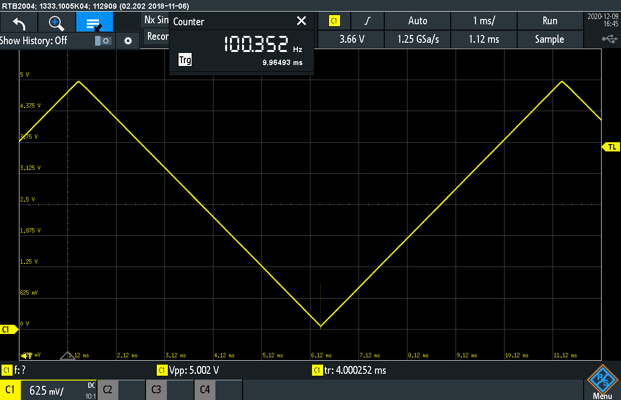 |
| 10kHz | |
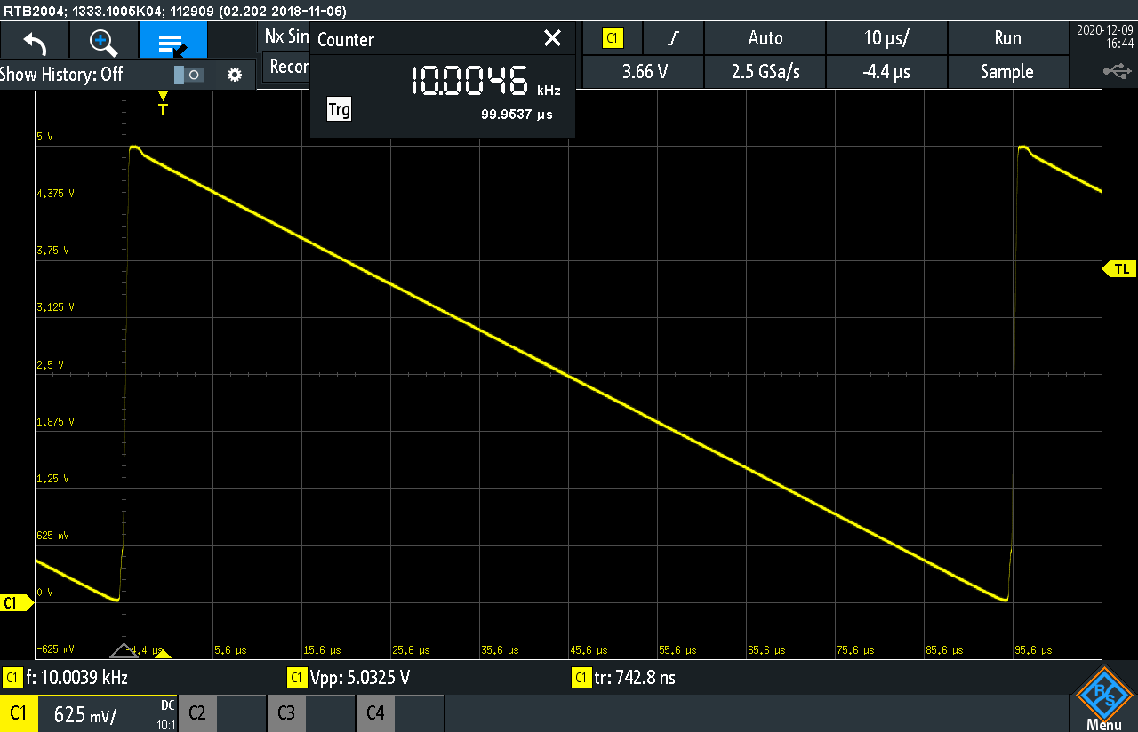 | 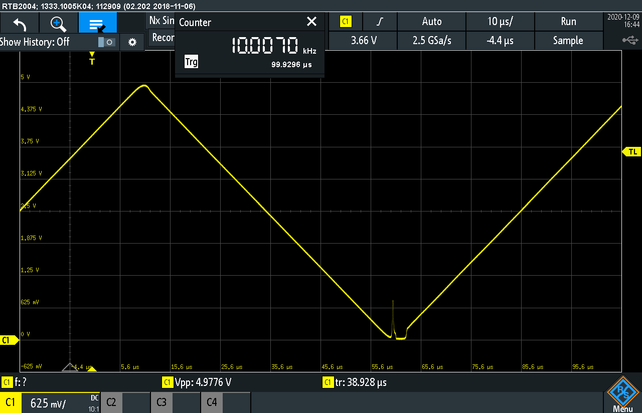 |
| maximum of this board, around 69kHz | |
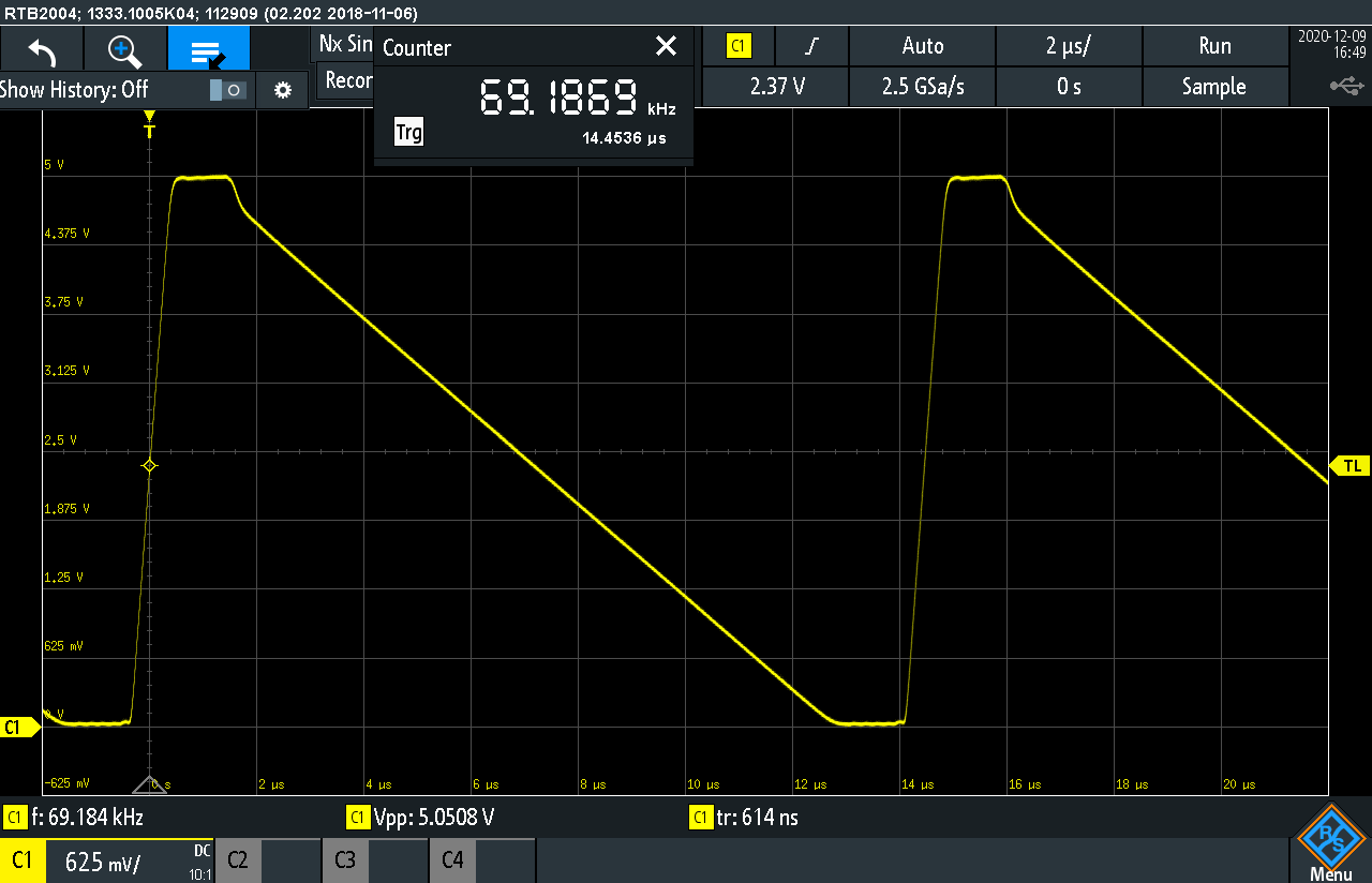 | 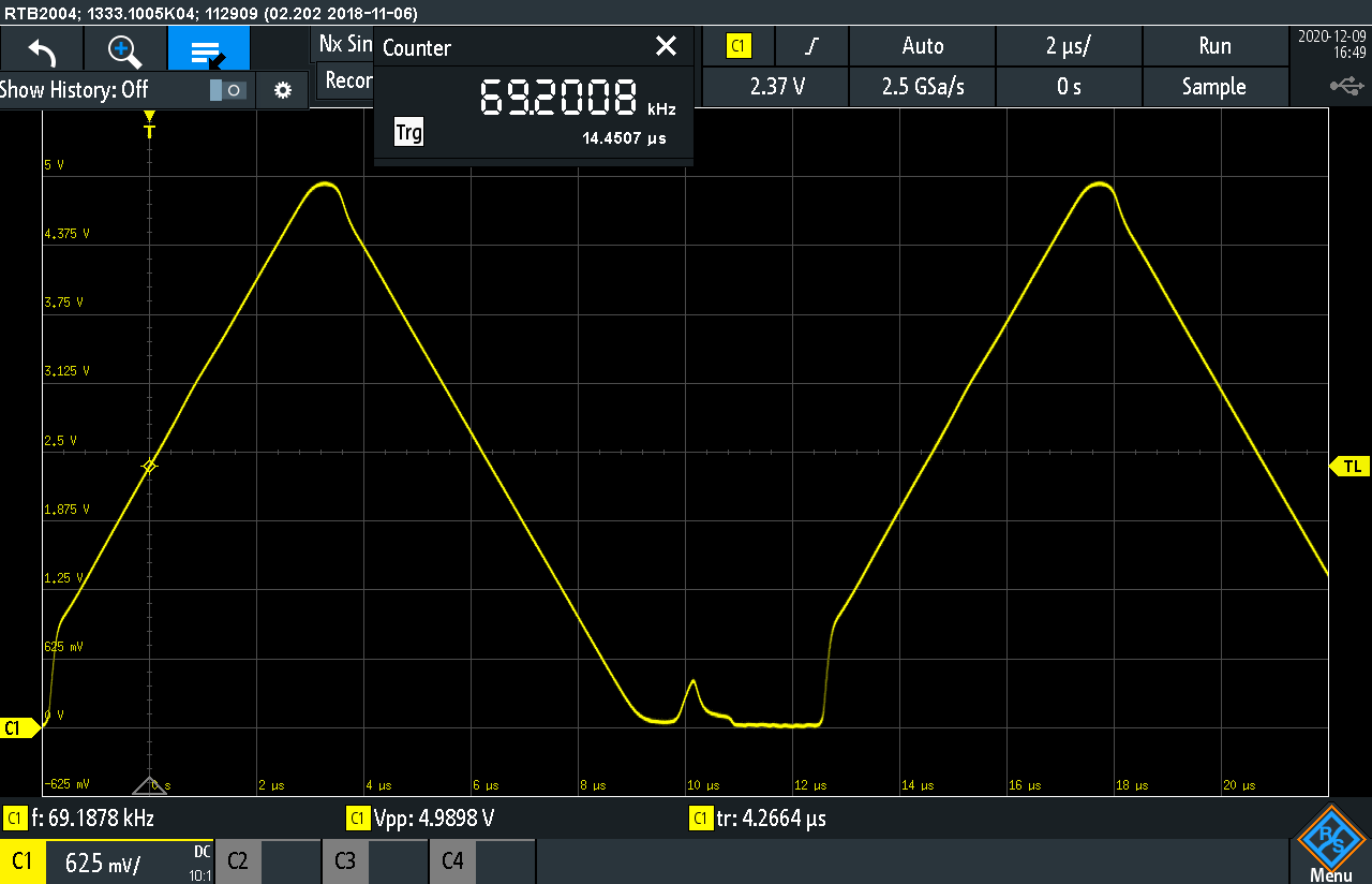 |
| sneak peek at the low side | |
| It is crucial to set proper divider ratios in the comparator to make the sawtooth go as low as possible. I can imagine sawtooth stepping down to 10mV or less, but it would require a trimmer to compensate for variation of 1% resistors used. In this scopeshot you can see it goes to 40mV at low frequencies, which is not bad at all, provided no resistors were selected. R1 is actually parallel connection of 1% 7.5k and 5% 47k resistors. At higher frequencies the ramp goes much lower, even as low as 17mV at 20kHz, this is because it takes some time before comparator toggles and transistor opens, this time is enough for the control current to charge the capacitor several tens of mV more | |
| low frequency | high frequency |
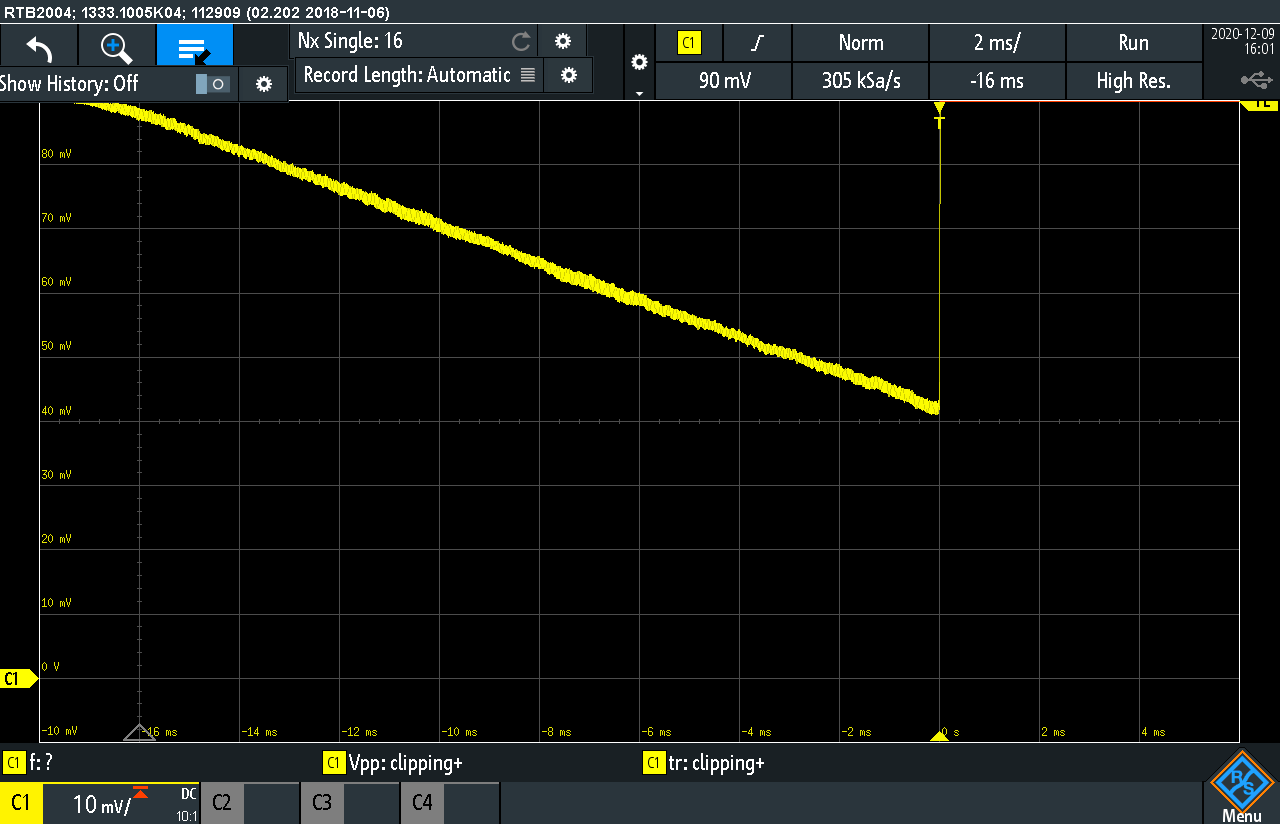 | 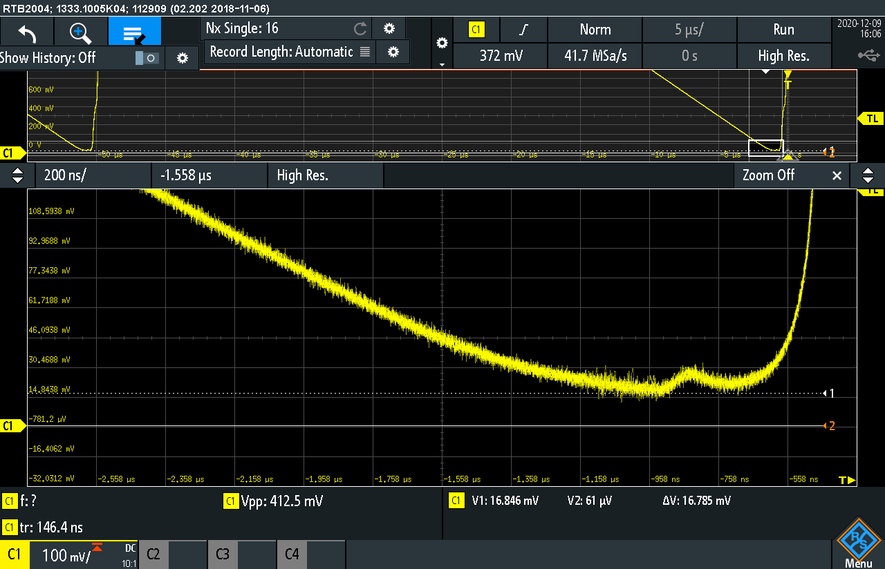 |
| same goes for upper edge of the sawtooth | |
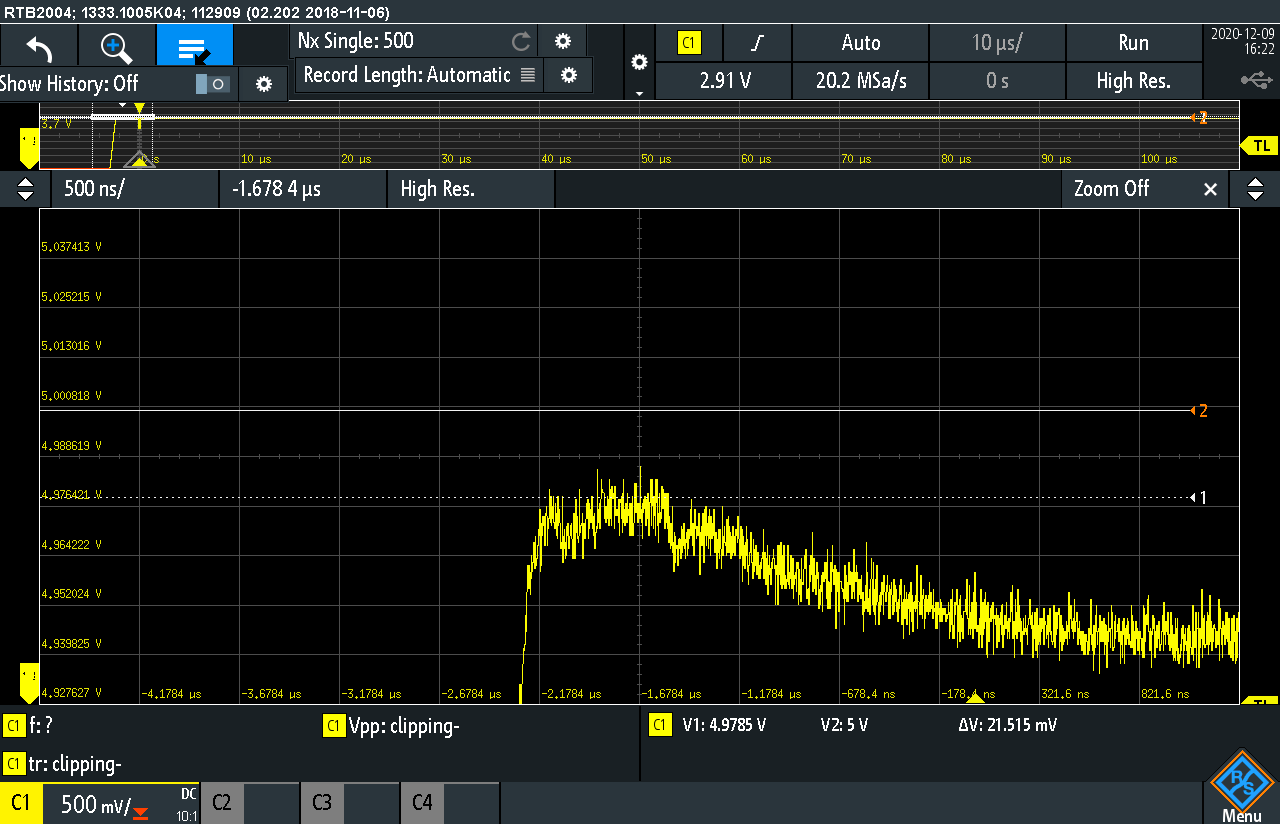 | 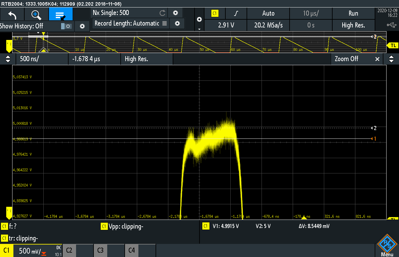 |
|
Let's talk about the triangle shaper now. It also takes advantage of rail-to-rail feature of the opamps. Instead of typical rectifying and level shifting,
here we feed the ramp into non-inverting amplifier with gain=2 (U1:C, R11, R12) referenced to 5V, so obviously at some point, exactly at the middle of ramp,
it will get saturated at GND. This then goes to inverting input of differential amplifier built with U1:D, R8, R15, T16, R13, R14. Non-inverting input
of this differential amplifier is fed by original ramp. As arithmetic magic happens, U1:D outputs pretty nice triangle. Unfortunately no matter how fast the opamps
would be, there is alwas a big spike (up to 5V) from the bottom of the triangle. This is when the ramp is reset. How lucky we are to have just what is needed
to clamp this thing down. Why not use the same signal that resets the integrator. T2 with R9-R10 holds the output down for those two microseconds when the spike
is coming. It would be nice to be able to omit R9 anr R10 and tie bases of T1 and T2 together, but when connected like that, the oscillator is totally messed up, unstable and ramp reaching barely 2V.
This is probably caused by C-B capacitance of T2 introducing some positive feedback to integrator. Putting decent high frequency
transistor as T2 could probably help, but I have to try that yet (as well as milion other things in life). So here are few scopeshots of the waveshaper. You saw the clean triangle above already, now let's focus on how dirty it is. | |
| time relation between sawtooth and triangle | |
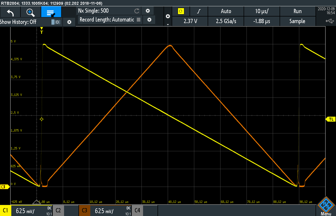
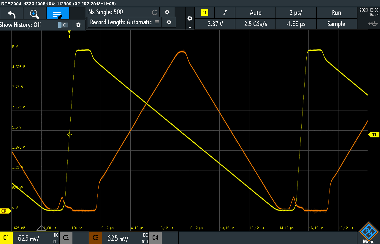
| At low frequencies the spike is difficult to spot, so let's skip that. Here are 10kHz and 70kHz cases. In latter one the action of T2 is clearly visible. The spike wants to jump up, but barely reaches 0.5V and T2 hits in, holds the line for about 2us, until the circuit is already in stable charging state. T2 opening causes this sudden jump of about 1V to catch the triangle running away. The triangle at 70kHz doesn't look good because of that, but who's going to hear that anyway? | |
| 10kHz | 70kHz |
 |  |
And here's the tiny little spike in more detail in case anyone's interested. It shows the spike is
really 0.77Vpp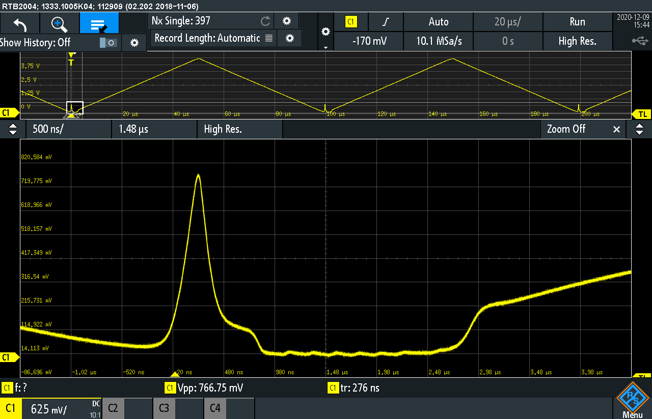 | |
| trapezoid waveshaper | |
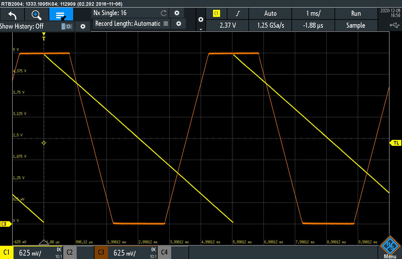
| The board pictured at top of this page contains very simple trapezoid waveshaper which is build using one rail-to-rail opamp with variable gain in a form of potentiometer in feedback path. It just overloads the triangle going throuogh the amplifier and clips at 0V and 5V. The slopes depend on gain. This is very simple circuit but sounds pretty nice, kinda like filtering. Here are 2 examples of its performance. By the way, the shaper and VCA are made with much slower opamp, so the triangle spike is wiped out completely then. | |
 |  |