| quad VCO |
| dual VC ADDSR |
| dual VCF |
| dual VCA |
| modulator |
| divider |
| mixer |
| sequencer |
| S&H |
| power supply |
| keyboard |
| MIDI2CV |
| SOUNDS |
|
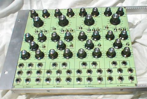
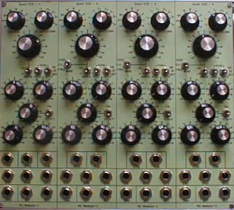
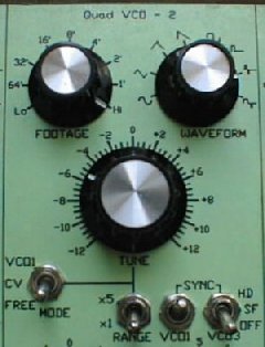
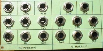
Panel
The panel consists of four separate strips (VCOs), each with the same controls except the first VCO. Each has the following:
- FOOTAGE switch:
- 64', 32', 16', 8', 4', 2', 1' plus 'Lo' 2 octaves below 64' and 'Hi' - something like 0.5'
- WAVEFORM switch:
- sine, triangle, minimoog ramp, saw, square, pulse, and 2 versions of bipolar pulses
- TUNE knob:
- tuning in range of +/-12 semitones or +/-5 octaves depending on RANGE switch
- MODE switch (VCO2,3,4 only):
- puts each VCO in one of three modes of tracking: free running, track CV0 input or track VCO1 tuning
- RANGE switch:
- sets the range of TUNE knob: 2 or 10 octaves
- SYNC switches (2):
- to activate synchronization between VCOs. 3 positions: off, soft, hard
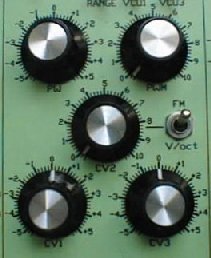
- PW knob:
- affects pulse width of three pulse waveforms and shape of sine (kinda like Synthi AKS)
- PWM knob:
- to control amount of PW modulation from PWM input
- CV1 and CV3 knobs:
- bipolar (+/-1) attenuators for CV1 and CV3 inputs affecting frequency (V/oct)
- CV2 knob:
- attenuator for CV2 input, may be switched between V/oct, and linear FM modes
- FM switch:
- determines type of modulation from CV2 input - V/oct, or linear FM
- INPUTS:
- CV1, CV2, CV3, PWM, SYNC
- OUTPUTS:
- SAW, OUT1, OUT2. OUTs 1,2 give waveform selected by WAVEFORM switch
Specifications
- Frequency range:
- 0.15Hz-60kHz with knobs, 0.006Hz-120kHz with external CV
- Output level:
- all outputs are 10Vpp around center GND. Pulse 0/+5V. Sine distorted with PW knob/input may decrease amplitude
- Interlock:
- in tests most of VCOs wouldn't interlock at few kHz with beat rate around 0.1Hz. For unknown reason VCO4 locks to VCO3 when beat rate is lower than 0.2Hz.
- Temperature drift:
- depending on frequency. 0.5%/C at 5kHz, which is bad news
- Center frequency:
- VCOs are tuned to 150Hz at 0V (FOOTAGE at 8', Tune in the middle, no ext CV)
- Short term stability:
- I made 4 hours test where two VCOs were set to 300Hz and 5kHz. 300Hz turned to 299.5 while 5kHz changed by 3Hz
Schematics
It doesn't differ much (electrically) from original, but is a little simplified (no VCAs) and few components changed. See the schematics
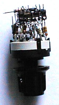
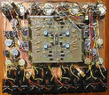
Construction
The panel is made of 2mm thick 2-sided copper platted glass epoxy. It is stiff enough, easy to work with, and you can
solder to it. All pots, switches and jacks are screwed directly to it - no middle panel. This way most of pots had to
go through shaft-cutting operation. Panel writings are made in PCB software, ink-printed on 250gsm colored paper,
painted with transparent acrylic spray, glued to panel. Inside are soldered 3 stands for securing PCB, and 4 taller
stands for attaching U shaped piece of brassplate as back cover. Power supply cable (+/-9V, +/-5V, GND and shield)
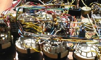
goes to power socket near PCB, where all wires meet. Ground leads of pots and switches are
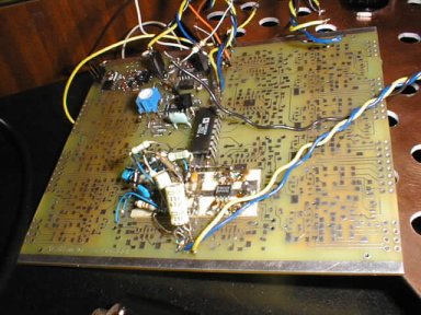
hooked with separate wires. The same (where possible) is done with power wires. This way I made sure to have real mess
inside (see photo below), but hopefully the module will be less susceptible to all kinds of interference, hum etc.
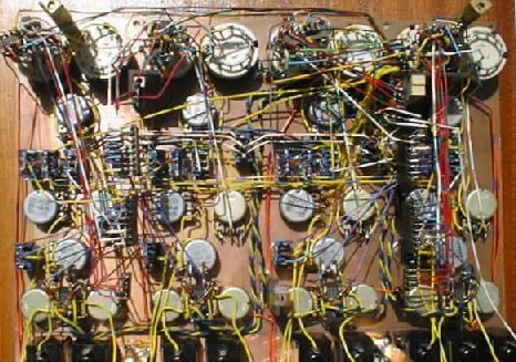
Because of new ideas popping up, the PCB hasn't covered all requirements (it was suppose to be prototype after all),
so I added some 3-D 'art' to it. Waveform selectors/shapers are built around switch leads - no protoboard or whatever.
Looks ugly, but works. Also CV1 and CV3 bipolar attenuators required some circuitry.
I decided to use more opamps instead of well known circuit and
obtain better resolution near 0, better attenuation at 0, no gain errors and constant input resistance. Those opamps are
soldered directly to pot's leads.
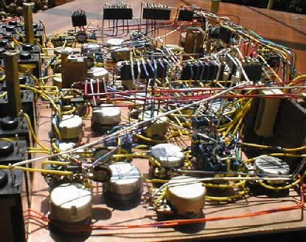
All this 3-D stuff resulted in reduction of wires inside module. I started with flexible wire, but then realized that
with solid wire I could achieve better results - once bent, the wire stays there. See what I mean in few photos below.
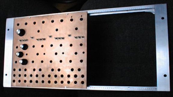
As for size standard, module fits into 5U 19''rack frame. Each VCO is 12TE wide (2.4''). I hope to make some page someday
with info on DIY racks, frames and keyboard stands.
Photos
top of module close-up
middle close-up
bottom close-up (jacks)
side view
back cover removed
pcb removed too
closer look from different angle
the prototype
5U 19'' frame with preliminary quad VCO front panel
Audio files
These are recordings of me tweaking the module recorded the same day I finished it, but it
took me almost a month to pick some of them put here. All are made solely with quadVCO module and
Polysynth used as CV keyboard (nonlinear, btw). MP3 encoder I used was not too good, and took half of life from every track. And please don't mind my lack of musical imagination ;-)
sine waves 718K heavily modulated
FM sound 266K sweeping and more
another FM sound 459K and bipolar pulse LFO
various FM noises 1.18M sweeping; stereo noise
in second half
few crazy patches 585K
unisono 411K two VCOs per channel
crazy tweakin' 880K
See also few scope screenshots of prototype waveforms